Differentiated Requirements for Magnetic Materials in Various Motors
- Material Requirements for Different Motor Types
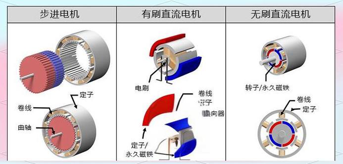
In motor applications, different types of motors have specific performance requirements for permanent magnets due to varying operating environments and application needs. Taking brushed DC motors and brushless DC (BLDC) motors as examples, while both commonly use magnet arcs (segments) or rings, significant technical differences exist in their magnetization processes. These differences primarily lie in magnetization methods, magnetic field distribution, and magnetization direction—key parameters that directly impact motor efficiency and operational characteristics.
When evaluating magnetization quality, three key parameters of the magnetization waveform offer important diagnostic value:
- Average Peak Value:Directly indicates whether the magnet’s magnetic performance meets design specifications.
- Peak-to-Peak Variation (Uniformity):Accurately represents the uniformity of the magnetization process.
- Waveform Area (or Duty Cycle):Under the same peak value conditions, this parameter determines the motor’s output characteristics. A larger value increases the motor’s cogging torque but reduces operational smoothness.
Together, these three parameters form a complete index system for judging magnetization quality, providing essential guidance for motor performance optimization.
Generally, brushed DC motors require high output torque, hence a larger waveform area (duty cycle) is preferred. Brushless DC motors, however, prioritize smooth rotation. A key metric for them is torque ripple, especially at low speeds. Smaller torque ripple requires a magnetization waveform closer to a sine wave. This is why we demand a magnetization waveform with a smooth, gradual rising edge.
- Pole Count Requirements for Different Motors
First, let’s review common magnetization types for magnet rings:
- External Magnetization:Magnet poles are created on the outer surface of the ring, typically used for motor rotors.
- Internal Magnetization:Magnet poles are created on the inner surface, typically used for motor stators or outer rotors.
- Skewed Magnetization:The magnet poles on the rotor surface form an angle of less than 90 degrees with the ring’s end faces.
- Axial Magnetization:Magnetization is along the axis of the ring or segment. This includes:
- Axial 2-pole:Simplest form, with one end as N pole and the other as S pole.
- Axial Single-Side Multi-pole:Mainly for magnet segments, where one surface has 2 or more poles.
- Axial Double-Side Multi-pole:Both surfaces have 2 or more poles with opposite polarity.
- Radial Magnetization:The magnetic field radiates from the center outwards. For a ring, this results in the entire inner surface being one polarity and the outer surface the opposite. For magnet arcs, radial magnetization often yields better performance than standard methods, making the surface flux density more uniform across the inner arc.
Regarding pole counts: 2-pole magnet rings are mostly used in small brushed DC motors, with some using 4 poles. Stepper, brushless DC, and synchronous motors use rings with even pole counts like 4, 6, 8, 10, etc.
III. Judging Application from Magnet Shape and Pole Count
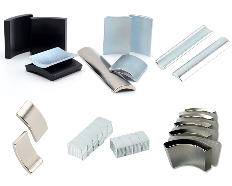
- Magnet Arcs (Segments):Primarily used in brushed and brushless DC motors.
- In brushed DC motors, 2-pole and 4-pole configurations are most common, identifiable by their large central angle (as previously mentioned).
- When used as the stator in BLDC motors, arcs typically have over 6 poles, resulting in a much smaller central angle.
- When used as the rotor in BLDC motors, arcs can have 4, 6, or more poles. A 4-pole rotor arc is magnetized on its outer surface and has a central angle close to 90° to form a complete circle, distinguishing it from brushed DC motor arcs.
- Magnet Rings:Mainly used to differentiate between stepper, brushless DC, and synchronous motors.
- Stepper Motor Rings:Typically have a small outer diameter (mostly around 20mm, rarely over 30mm), thin wall thickness (1.0-1.5mm), and a high pole count (over 10 poles, sometimes up to 50).
- BLDC Motor Rings:Generally have a diameter >20mm, pole counts between 4-12, and wall thickness between 1.5-5.0mm.
- Small Synchronous Motor Rings:Diameter between 20-40mm, pole counts 8-16, and wall thickness 1.0-3.0mm.
- Application Characteristics of Different Performance Parameters
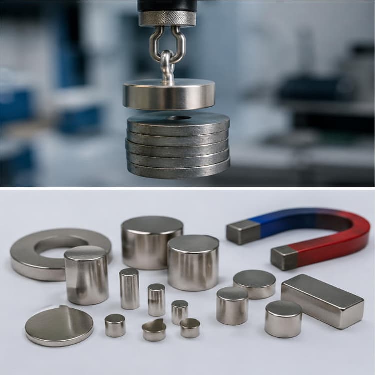
Injection-molded magnets, bonded NdFeB, and sintered NdFeB are three common materials for small motors, especially the first two. Their performance and cost increase in that order, defining their respective applications.
- Injection-Molded Magnets:Include ferrite and NdFeB Injection-molded ferrite can be isotropic or anisotropic. Isotropic grades have lower energy product (~1.5 MGOe), while anisotropic grades reach ~2.1 MGOe. Injection-molded NdFeB has a maximum energy product of ~6.0 MGOe (up to ~6.5 MGOe with imported raw materials, but at higher cost). Its application is not yet widespread.
- Bonded NdFeB:The most widely used in high-performance applications, bridging the gap between sintered NdFeB and ferrite products due to its intermediate performance. Being isotropic, it suits various magnetization methods. Its main limitation is a maximum operating temperature of 150°C, making it ideal for small motors and control motors. Suitability for drive motors depends on specific conditions.
- Sintered NdFeB:Widely used for its high performance, currently primarily in drive motors like BLDC and AC servo motors, mainly in arc shapes. This is because standard sintered NdFeB is uniaxially oriented, allowing magnetization in only one direction, thus limiting rings to 2-pole magnetization. Newly developed radially oriented sintered NdFeB overcomes this. The difference lies in the orientation direction during pressing, but radial product tooling is more complex and incurs mold costs.
- How to Judge Magnetic Material Quality from Motor Operation Results
- Motor Torque:Generally, higher torque indicates higher magnet performance, and vice versa. In small motors, lower detent torque (the torque required to start the motor from rest) is desired, which is mainly determined by the magnetization waveform and stator core slot shape.
- Motor Speed:Includes no-load and load speeds. When correlating speed with magnet performance, exclude influences from other motor resistance torques.
- Higher no-load speed suggests lower magnetic performance, and vice versa.
- Higher load speed suggests higher magnetic performance, and vice versa.
- Motor Current:Includes no-load and load currents. Similarly, exclude other resistance torques when assessing.
- Larger no-load current suggests lower magnetic performance, and vice versa, although this is less pronounced as no-load current relates more to winding resistance.
- Larger load current suggests lower magnetic performance, and vice versa.