The largest application area for magnets is in electric motors, which are electrical devices based on the principle of electromagnetic induction. An air gap magnetic field is a prerequisite for generating electromagnetic induction. Motors that use permanent magnets to create the air gap magnetic field are called permanent magnet motors. These motors do not require additional electrical energy input or extra windings, making them compact, structurally simple, energy-efficient, and widely applicable.
In this video, let’s explore the magnets used in permanent magnet motors. The rotating part of a motor is called the rotor, while the stationary part is the stator. When magnets serve as the stator magnetic field source, they are often shaped as arc segments (tile-shaped) and attached to the inner surface of the motor casing. When magnets function as the rotor magnetic field source, they are typically attached to the rotor core as inner arc segments or embedded into the rotor core as rectangular pieces.
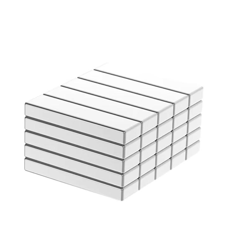
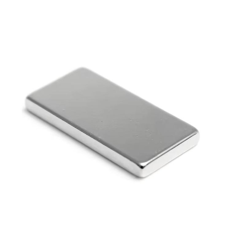
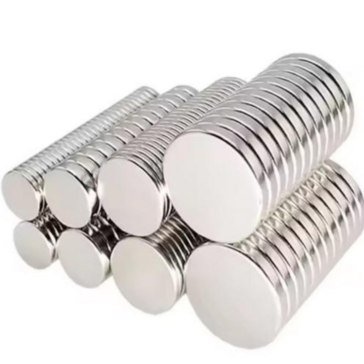
The shapes of magnets used in permanent magnet motors are generally simple, with rectangles, arcs, sectors, and bread-loaf shapes being the most common. In the context of cost reduction in motor design, embedded rectangular magnets are currently the mainstream choice due to their simpler magnetization process. They are usually magnetized with a single pole and assembled to form multi-pole magnetic circuits. If integrated magnetic rings—such as bonded neodymium rings or hot-pressed magnetic rings—are used, they are often radially multi-pole magnetized. Magnets for motors span low, medium, and high grades of magnetic energy, though most exhibit medium to high coercivity levels.
Currently, magnets for electric vehicle drive motors mainly feature high magnetic energy and high coercivity grades, such as 45UH, 42EH, and 45EH. Key technical indicators for motor magnets include high-temperature stability, magnetic flux consistency, and dimensional compatibility. During motor operation, magnets are subjected not only to high temperatures but also to alternating reverse magnetic fields. Therefore, it is essential to test and monitor the demagnetization curves of finished magnets and base materials at elevated temperatures. As the source of the magnetic field in the rotor or stator, magnets generally require consistent magnetic flux—some within 5% tolerance, and stricter cases within 2%. Consistency in remanence, dimensional tolerances, and chamfer layers all affect magnetic flux uniformity and must be carefully controlled.
For tile-shaped magnets, which are commonly used in surface-mounted designs, conventional measurement methods often result in significant errors or difficulties in testing angles and curvatures. It is recommended to customize fixture tools that simulate the user’s assembly method to verify the compatibility of the magnets.